9_Rendering 3D Scenes
In this lesson, we implement some basic Geometry and Material classes for rendering a spinning box, and then introduce some extra components to aid in the design and development of 3D scenes.
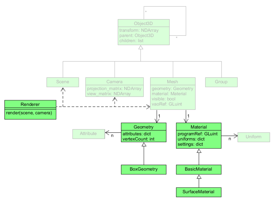
In the previous lesson, we outlined the scene graph components for our framework and created many of the basic components, including Object3D, Scene, Group, Camera, and Mesh.
At that time, we also created empty classes for Geometry and Material.
Now we will finish implementing Geometry and Material in full detail and demonstrate their use with some basic extensions.
This time we will make the classes BoxGeometry, BasicMaterial, and SurfaceMaterial which will allow us to render a 3D box with sides of different colors.
The BoxGeometry class will store different color values for each vertex separately so that it is easier to see the box clearly when it’s rendered.
If every side were to be the same color, there would be no way to distinguish the sides and see the edges of the box.
The BasicMaterial class provides the basic features of every material, namely vertex shader code that makes use of our transformation matrices and fragment shader code that allows for different vertex colors.
The shader program also includes a default base color set to white initially which can be used when we want all sides to be the same color.
Each extension of the BasicMaterial class will manage its own OpenGL render settings for its specific style of drawing such as points, lines, or triangle.
Once we have a basic geometry and material to use in a Mesh, we will then create the Renderer class that can draw every Mesh using Scene and Camera objects.
Then we will have all the components we need to draw a 3D box in a test application.
Geometry Objects
The Geometry class contains a dictionary of Attribute instances that represent the geometric features of a 3D object to be rendered.
As a base class, it only holds the shared properties and behaviors of all geometric objects.
Specific details about vertex data and attributes for certain types of geometric objects will be managed by their respective extensions of Geometry.
![]() Try it!
Try it!
Open your geometry.py file from the graphics/geometries folder.
Delete the word pass inside the Geometry class and add the following code:
    def __init__(self):
        self._attributes = {}

    @property
    def attributes(self):
        return self._attributes

    @property
    def vertex_count(self):
        return self.count_vertices()

    def set_attribute(self, variable_name, data, data_type=None):
        """
        Add or update an attribute for this geometric object.
        A `data_type` must be provided when making a new attribute.
        No `data_type` is needed when updating an existing attribute.
        """
        if variable_name in self._attributes:
            self._attributes[variable_name].data = data
            self._attributes[variable_name].upload_data()
        elif data_type is not None:
            self._attributes[variable_name] = Attribute(data_type, data)
        else:
            raise ValueError("New attributes must have a data type.")

    def count_vertices(self, variable_name=None):
        """
        Count the number of vertices in an attribute's data.
        If no `variable_name` is provided, the first attribute will be used.
        """
        if len(self._attributes) == 0:
            return 0

        if variable_name is not None:
            attrib = self._attributes.get(variable_name)
            if attrib is None:
                raise ValueError(variable_name, "Attribute not found")
            return len(attrib.data)
        else:
            return len(list(self._attributes.values())[0].data)
Make sure there are no errors and save the file.
The _attributes dictionary will store instances of Attribute for each variable in the shader program.
Since variable names are unique, we can use them as the key for the associated attribute.
The set_attribute method updates data for an existing Attribute or creates a new one.
We want to manage a reference to the attributes dictionary internally, so we name it with an underscore, as in _attributes, and create a getter property to allow external access.
After an attribute has been set, we can use the count_vertices method to get the number of vertices.
The vertex_count property will call count_vertices everytime so Geometry.vertex_count will always give us an up-to-date value.
Properties are useful for providing simplified interfaces to complex internal behavior in this way.
Now that we have the base Geometry defined, we can create our first geometric objects: 2D rectangles and 3D boxes.
Rectangles
The first geometric object we will create is a simple 2D rectangle with its origin at the center of its area.
The RectangleGeometry class will take two parameters—the width and height that define the two sides of the rectangle.
Since its origin is at the center, we can find the $x$ and $y$ coordinates of its four vertices from the provided height and width values.
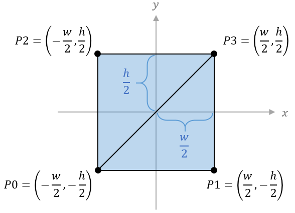
Since the only way to draw filled-in shapes with OpenGL is with triangles, our rectangles need to be defined as two right triangles that share the same hypotenuse. This means that we need to define groups of vertices for each triangle separately, giving us a total of six vertices instead of four. Also, the vertices must be listed in counterclockwise order so that the front sides of the triangles face in the positive $z$ direction.
![]() Try it!
Try it!
In the graphics/geometries folder, create a new file called basic_geometries.py.
Open the __init__.py file in the graphics/geometries folder and add the following code:
from graphics.geometries.basic_geometries import *
Open the basic_geometries.py file for editing and add the following code:
# graphics/geometries/basic_geometries.py
from graphics.geometries.geometry import Geometry

class RectangleGeometry(Geometry):
    """A rectangle with the given width and height, and a center at (0, 0)"""
    def __init__(self, width=1, height=1):
        super().__init__()

        w, h = width/2, height/2

        # position vertices
        P0 = (-w, -h, 0)
        P1 = ( w, -h, 0)
        P2 = (-w,  h, 0)
        P3 = ( w,  h, 0)

        # color data for white, red, green, and blue vertices
        C0 = (1, 1, 1)
        C1 = (1, 0, 0)
        C2 = (0, 1, 0)
        C3 = (0, 0, 1)

        position_data = (
            P0, P1, P3,  # first triangle
            P0, P3, P2   # second triangle
        )
        color_data = (
            C0, C1, C3,  # first triangle
            C0, C3, C2   # second triangle
        )

        self.set_attribute("vertexPosition", position_data, "vec3")
        self.set_attribute("vertexColor", color_data, "vec3")
Make sure there are no errors and save the file.
The color vertices are listed in the same order as the position vertices. Here we make sure that the shared vertices of the two triangles are the same color so that there is a smooth gradient between them. If the color vertices did not align, then we would be able to see a clear divide between the colors running diagonally through the rectangle.
Boxes
Our first 3D shape will be a box with eight points and six sides.
Since each side must be drawn as two triangles, we must group our vertices to form a total of 12 triangles.
And since each triangle is a collection of three points, the position and color data will have a total of 36 vertices each.
As with the rectangle, our BoxGeometry class will only take the shape’s dimensions as parameters—the width, height, and depth.
These define the lengths of the sides parellel to the $x$, $y$, and $z$ axes respectively.
Again, we will calculate the $x$, $y$, and $z$ coordinates of the vertices from these parameters since the origin of the box will be at the center of its volume.
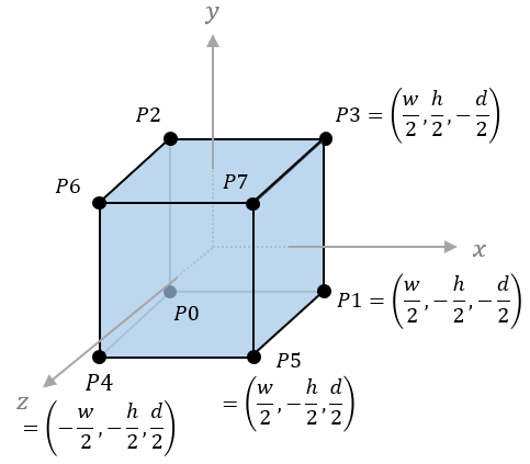
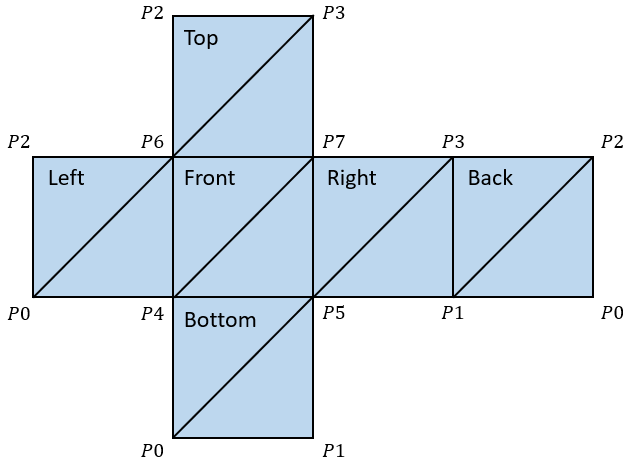
As before, we need to be careful about the ordering of the vertices. Each triangle group must list the vertices in counterclockwise order with respect to the outward facing direction of the surface. For example, the front side of the box will have vertices in order of $(P4, P5, P7)$ and $(P4, P7, P6)$ but the vertices of the back-facing side will be in order of $(P1, P0, P2)$ and $(P1, P2, P3)$. It may be easier to visualize this if we “unfold” the 3D shape so all the surfaces are arranged facing towards the viewer on a flat plane. The resulting image is called a net diagram and it helps us to easily see the correct ordering of the vertices.
![]() Try it!
Try it!
In the basic_geometries.py file, add the following code after the RectangleGeometry class:
class BoxGeometry(Geometry):
    """A 3D box centered at its origin with given width, height, and depth"""
    def __init__(self, width=1, height=1, depth=1):
        super().__init__()

        w, h, d = width/2, height/2, depth/2

        # position vertices
        P0 = (-w, -h, -d)
        P1 = ( w, -h, -d)
        P2 = (-w,  h, -d)
        P3 = ( w,  h, -d)
        P4 = (-w, -h,  d)
        P5 = ( w, -h,  d)
        P6 = (-w,  h,  d)
        P7 = ( w,  h,  d)

        # color vertex data for each side
        C1 = [(1, 0, 0)] * 6   # six red vertices
        C2 = [(1, 1, 0)] * 6   # six yellow vertices
        C3 = [(0, 1, 0)] * 6   # six green vertices
        C4 = [(0, 1, 1)] * 6   # six cyan vertices
        C5 = [(0, 0, 1)] * 6   # six blue vertices
        C6 = [(1, 0, 1)] * 6   # six magenta vertices

        position_data = (
            P5, P1, P3,  P5, P3, P7,  # right side
            P0, P4, P6,  P0, P6, P2,  # left side
            P6, P7, P3,  P6, P3, P2,  # top side
            P0, P1, P5,  P0, P5, P4,  # bottom side
            P4, P5, P7,  P4, P7, P6,  # front side
            P1, P0, P2,  P1, P2, P3   # back side
        )

        # create a list of 36 RGB vertices
        color_data = C1 + C2 + C3 + C4 + C5 + C6

        self.set_attribute("vertexPosition", position_data, "vec3")
        self.set_attribute("vertexColor", color_data, "vec3")
Make sure there are no errors and save the file.
Again, the order of the vertex color data will decide the color of each side.
The six red vertices are first, so they are assigned to the right side.
Then the left side gets yellow vertices, the top side gets green, the bottom side gets cyan, the front side gets blue, and the back side gets magenta.
These sides will be solid colors, so each side must have the same color for each of its six vertices.
We took advantage of the * operator to multiply the lists and create six copies of each color vertex.
If we wanted to see color gradients on each side, we would need to write out each color vertex similar to the way we write out each position vertex.
Material Objects
While Geometry classes manage geometric data concerning the position and color of a 3D object’s vertices, the Material classes manage data related to the rendering approach for the object, including the shader program, Uniform objects, and OpenGL render settings.
The Material Class
The Material base class will compile and initialize the shader program, store and manage uniform objects in a dictionary, and keeps OpenGL-specific settings in another dictionary.
![]() Try it!
Try it!
Open your material.py file inside the graphics/materials folder.
Delete the word pass inside the Material class and add the following code:
    def __init__(self, vertex_shader_code, fragment_shader_code):
        self._program_ref = initialize_program(vertex_shader_code, fragment_shader_code)

        self._uniforms = {}

        # common shader uniforms used in the render process
        self.set_uniform("modelMatrix", None, "mat4")
        self.set_uniform("viewMatrix", None, "mat4")
        self.set_uniform("projectionMatrix", None, "mat4")

        # OpenGL render settings
        self._settings = {"drawStyle": GL.GL_TRIANGLES}

    @property
    def program_ref(self):
        return self._program_ref

    def get_setting(self, setting_name):
        """Return a setting value if the setting exists; otherwise, return None"""
        return self._settings.get(setting_name, None)
Each extension of the Material class can define its own vertex and fragment shader code which it will then pass to the superclass __init__ method.
Here we assume that the shader program will include uniform variables for modelMatrix, viewMatrix, and projectionMatrix.
We create and store associations for those variables with Uniform objects in a method called set_uniform which we define below.
We also provide a getter for the program reference which will be necessary for the Mesh class to associate attribute variables in the program and then draw each object.
Next, add the following code to the Material class for managing uniform objects and OpenGL settings:
    def set_uniform(self, variable_name, data, data_type=None):
        """
        Set or add a Uniform object representing a property of this material.
        A `data_type` must be provided when creating a new uniform.
        No `data_type` is required when updating an existing uniform.
        """
        if variable_name in self._uniforms:
            self._uniforms[variable_name].data = data
        elif data_type is not None:
            self._uniforms[variable_name] = Uniform(data_type, data)
            self._uniforms[variable_name].locate_variable(
                self._program_ref, variable_name
            )
        else:
            raise ValueError("New uniforms must have a data type.")

    def upload_data(self):
        """Upload the data of all stored uniform variables"""
        for uniform_obj in self._uniforms.values():
            uniform_obj.upload_data()

    def set_properties(self, properties):
        """Set multiple uniforms and settings from a dictionary"""
        for name, data in properties.items():
            if name in self._uniforms:
                self._uniforms[name].data = data
            elif name in self._settings:
                self._settings[name] = data
            else:
                raise ValueError(f"Material has no property named {name}")

    def update_render_settings(self):
        pass
Make sure there are no errors and save the file.
The set_uniform method will update the data of an existing variable similar to the set_attribute method in the Geometry class.
The difference here is that uniforms variables must be located in the program before their data can be uploaded, so the set_uniform method immediately locates any new Uniform object it creates.
Then, the separate upload_data method updates all the uniform variable data linked in the program, which we will call from the Mesh class after setting the our transformation matrices data.
The set_properties method is provided as a convenience so we can pass in all our uniforms and settings together in a single dictionary.
The update_render_settings method is empty here so that subclasses of Material can override it.
The method will check for specific render settings in its self._settings dictionary and then call the relevant OpenGL functions based on the setting values.
Basic Materials
In our hierarchy of materials, the BasicMaterial class is a direct child of Material and its purpose is to provide the vertex shader code and fragment shader code for rendering points, lines, and surfaces.
The shader program will be relatively simple with uniform variables for the projection matrix, view matrix, and model matrix along with attribute variables for the vertex position, and vertex color data.
![]() Try it!
Try it!
In the graphics/materials folder, create a new file called basic_materials.py.
Open the __init__.py file in the graphics/materials folder and add the following code:
from graphics.materials.basic_materials import *
Open basic_materials.py for editing and add the following code:
# graphics/materials/basic_materials.py
import OpenGL.GL as GL

from graphics.materials.material import Material

_VERTEX_SHADER_CODE = """
uniform mat4 projectionMatrix;
uniform mat4 viewMatrix;
uniform mat4 modelMatrix;

in vec3 vertexPosition;
in vec3 vertexColor;

out vec3 color;

void main() {
    gl_Position = projectionMatrix * viewMatrix * modelMatrix * vec4(vertexPosition, 1.0);
    color = vertexColor;
}
"""

_FRAGMENT_SHADER_CODE = """
uniform vec3 baseColor;
uniform bool useVertexColors;

in vec3 color;

out vec4 fragColor;

void main() {
    vec4 tempColor = vec4(baseColor, 1.0);
    if (useVertexColors) tempColor *= vec4(color, 1.0);
    fragColor = tempColor;
}
"""


class BasicMaterial(Material):
    """A simple material for rendering objects in a solid color or vertex colors."""
    def __init__(self):
        super().__init__(_VERTEX_SHADER_CODE, _FRAGMENT_SHADER_CODE)

        self.set_uniform("baseColor", (1, 1, 1), "vec3")
        self.set_uniform("useVertexColors", False, "bool")
Make sure there are no errors and save the file.
Here we define the vertex shader and fragment shader code that will be used by all basic materials.
Then we define the BasicMaterial class as a subclass of Material and call the superclass __init__ method with the shader code to initialize the shader program.
Then we provide a default color (white) for the baseColor uniform variable in the shader program.
In our apps, we will be able to override this color by setting useVertexColors to True and supplying vertex color data to the vertexColor attribute.
Now that the shader program is set, we can create subclasses that handle specific render settings by implementing the update_render_settings method.
Point Material
The first extension of our BasicMaterial class will render vertices as disconnected points.
It will define settings for drawStyle and pointSize to call the appropriate OpenGL functions.
![]() Try it!
Try it!
Open basic_materials.py for editing and add the following code after the BasicMaterial class:
class PointMaterial(BasicMaterial):
    """
    Manages render settings for drawing vertices as rounded points.
    The following rendering properties are supported.
    - drawStyle: the OpenGL draw setting (default is `GL_POINTS`)
    - pointSize: the width and height of each point in pixels (default is `8`)
    """
    def __init__(self, properties=None):
        super().__init__()

        self._settings["drawStyle"] = GL.GL_POINTS
        self._settings["pointSize"] = 8

        if properties:
            self.set_properties(properties)

    def update_render_settings(self):
        GL.glPointSize(self._settings["pointSize"])
Make sure there are no errors and save the file.
The drawStyle setting is used by the Mesh class, but the update_render_settings method handles all other OpenGL settings.
Here we set the point size with glPointSize and enables smooth points with glEnable.
Line Material
The next extension will enable drawing different line styles as defined by the lineType setting.
The “connected” type draws lines through each vertex, from the first to the last.
The “loop” type will additionally draw a final line from the last vertex back to the first vertex.
The “segments” type will draw separate lines between consecutive pairs of vertices.
![]() Try it!
Try it!
Open basic_materials.py for editing and add the following code after the PointMaterial class:
class LineMaterial(BasicMaterial):
    """
    Manages render settings for drawing lines between vertices.
    The following render properties are supported.
    - lineType "connected": draws through all vertices from first to last
    - lineType "loop": draws through all vertices and connects last to first
    - lineType "segments": draws separate lines between each pair of vertices
    """
    def __init__(self, properties=None):
        super().__init__()

        self._settings["lineType"] = "connected"

        if properties:
            self.set_properties(properties)

    def update_render_settings(self):
        if self._settings["lineType"] == "connected":
            self._settings["drawStyle"] = GL.GL_LINE_STRIP
        elif self._settings["lineType"] == "loop":
            self._settings["drawStyle"] = GL.GL_LINE_LOOP
        elif self._settings["lineType"] == "segments":
            self._settings["drawStyle"] = GL.GL_LINES
        else:
            raise ValueError("Unknown line type: must be one of (connected, loop, segments).")
Make sure there are no errors and save the file.
The lineType setting defines values for the drawStyle setting to align with those supported by this material.
The values “connected”, “loop”, and “segments” are easier to understand than the OpenGL draw style constants of GL_LINE_STRIP, GL_LINE_LOOP, and GL_LINES.
Additionally, we restrict the draw styles that can be used with this class by explicitly checking the value of the lineType property.
Surface Material
The last extension will draw triangles between every three vertices to create a tiled surface. The front side of a surface is the one for which the vertices are drawn in counterclockwise order. OpenGL does not render the back side of a surface by default, but it does have a setting to render both sides. We will create a control parameter for this with the “doubleSide” setting. Additionally, we will make a “wireframe” setting for rendering only the lines of the surfaces without filling in the space between them.
![]() Try it!
Try it!
Open basic_materials.py for editing and add the following code after the LineMaterial class:
class SurfaceMaterial(BasicMaterial):
    """
    Manages render settings for drawing vertices as a colored surface.
    The following render properties are supported.
    - drawStyle: the OpenGL draw setting (default is `GL_TRIANGLES`)
    - doubleSide: renders both sides of the surface (default is `False`)
    - wireframe: renders just the triangle outlines (default is `False`)
    """
    def __init__(self, properties=None):
        super().__init__()

        self._settings["drawStyle"] = GL.GL_TRIANGLES
        self._settings["doubleSide"] = False
        self._settings["wireframe"] = False

        if properties:
            self.set_properties(properties)

    def update_render_settings(self):
        if self._settings["doubleSide"]:
            GL.glDisable(GL.GL_CULL_FACE)
        else:
            GL.glEnable(GL.GL_CULL_FACE)

        if self._settings["wireframe"]:
            GL.glPolygonMode(GL.GL_FRONT_AND_BACK, GL.GL_LINE)
        else:
            GL.glPolygonMode(GL.GL_FRONT_AND_BACK, GL.GL_FILL)
Make sure there are no errors and save the file.
Now that we have created some geometry and material classes, we are a lot closer to being able to rendering objects. The last thing required is a class that controls how each mesh object renders with the camera.
Rendering Scenes with the Framework
The Renderer class is the last necessary component for rendering 3D scenes.
It will initialize all the components of the scene including the camera and mesh objects.
Then it sets up and manages general processes for the scene such as depth testing, antialiasing, and clearing each frame.
![]() Try it!
Try it!
In the graphics/core folder, create a new file called renderer.py.
Open renderer.py for editing and add the following code:
# graphics/core/renderer.py
import OpenGL.GL as GL

from graphics.core.scene_graph import Mesh, Camera, Scene

class Renderer:
    """Manages the rendering of a given scene with basic OpenGL settings"""
    def __init__(self, scene, camera, clear_color=(0, 0, 0)):
        if not isinstance(scene, Scene):
            raise ValueError("The given scene must be of type Scene.")
        if not isinstance(camera, Camera):
            raise ValueError("The given camera must be of type Camera.")

        if type(clear_color) not in {tuple, list}:
            raise ValueError("Clear color must be a tuple or list.")
        if len(clear_color) != 3:
            raise ValueError("Clear color must contain RGB values.")

        self.scene = scene
        self.camera = camera

        # Enable depth testing and antialiasing
        GL.glEnable(GL.GL_DEPTH_TEST)
        GL.glEnable(GL.GL_MULTISAMPLE)

        # unpack the values of clear_color to pass in separately
        GL.glClearColor(*clear_color, 1)

    def render_scene(self):
        """Render the given scene as viewed through the given camera"""
        # clear buffers
        GL.glClear(GL.GL_COLOR_BUFFER_BIT | GL.GL_DEPTH_BUFFER_BIT)

        # draw all the viewable meshes
        for mesh in self.scene.descendant_list:
            if isinstance(mesh, Mesh) and mesh.visible:
                mesh.render(
                    self.camera.view_matrix,
                    self.camera.projection_matrix
                )
Make sure there are no errors and save the file.
The Renderer encapsulates scene and camera objects which are provided when initialized.
It also enables OpenGL settings that are universal for the scene, such as depth testing and antialiasing.
The clear color is effectively the background color for each frame, so we also set it here after checking to make sure a proper data structure of RGB values is provided.
The actual rendering happens when we call render_scene on the Renderer object after creating it.
That method uses the object’s scene and camera to render every visible mesh.
Since the Scene is the root node of a scene graph, we can get every mesh in the scene by using its descendant_list property.
Then we can call render on every visible mesh with the view matrix and projection matrix defined by the camera.
Remember, each individual mesh handles the steps for rendering itself. These steps are:
- Specify the shader program to use for rendering from a material object.
- Bind the VAO that holds the links between shader variables and data.
- Set the model, view, and projection matrices.
- Upload data to the uniform variables (such as matrices).
- Update OpenGL render settings.
- Draw each vertex defined by the goemetry object in the style of the material object.
All these steps we already programmed into the render method of the Mesh class in the previous lesson. (See the final code snippet in The Scene Graph.)
With the Renderer object complete, now we can finally render a 3D scene.
Let’s make a simple spinning cube in the center of the screen using the BoxGeometry and SurfaceMaterial classes.
![]() Try it!
Try it!
In your main working folder, create a new file called test_9_1.py.
Open test_9_1.py for editing and add the following code:
# test_9_1.py
from math import pi

from graphics.core.app import WindowApp
from graphics.core.renderer import Renderer
from graphics.core.scene_graph import Scene, Camera, Mesh
from graphics.geometries import BoxGeometry
from graphics.materials import SurfaceMaterial

class Test_9_1(WindowApp):
    """Test basic scene graph elements by rendering a spinning cube"""
    def startup(self):
        print("Starting up Test 9-1...")

        scene = Scene()
        camera = Camera(aspect_ratio=4/3)
        camera.position = (0, 0, 4)
        self.renderer = Renderer(scene, camera)

        geometry = BoxGeometry()
        material = SurfaceMaterial({"useVertexColors": True})
        self.mesh = Mesh(geometry, material)
        scene.add(self.mesh)

        self.rotate_speed_Y = 2/3 * pi
        self.rotate_speed_X = 1/3 * pi

    def update(self):
        self.mesh.rotate_y(self.rotate_speed_Y * self.delta_time)
        self.mesh.rotate_x(self.rotate_speed_X * self.delta_time)

        self.renderer.render_scene()

# initialize and run this test at 800 x 600 resolution
Test_9_1(screen_size=(800,600)).run()
Save the file and run it with the command python test_9_1.py in the terminal.
Confirm that you can see a spinning cube in the center of the screen with different colors on every side.
Our test apps are quite a bit shorter now! This is the advantage of encapsulating common rendering tasks in scene graph components.
The startup method creates a Scene and Camera with 4:3 aspect ratio before passing them to a new Renderer object.
Then it creates a box geometry, and a surface material with different colored vertices.
It combines the geometry and material in a mesh object before adding the mesh to the scene graph.
Finally, it sets different speeds for the box to rotate around both the $x$-axis and the $y$-axis.
After everything is set up, the update method simply applies the rotations to the mesh before rendering the entire scene.
Extra Components
Now that all the necessary components for rendering basic shapes are complete, we can create helper objects that make it easier to design a 3D scene. All of our scenes so far have just been shapes floating in a black void. Let’s change that by creating a structure to reveal the global coordinate axes and a grid to orient the user. After rendering these objects in a scene, we will also create a rig for the camera that allows the user to control camera movements and explore the scene.
Axes Helper
To visualize the three coordinate axes, we will create three box geometries—one for each axis.
The BoxGeometry class allows us to specify the thickness of each axis which is something we would not be able to do if we wanted to just draw lines with the glLineWidth function (due to its incompatibility on MacOS).
Here we can use our Group class for the base mesh and add children to it for each of the three separate axes.
![]() Try it!
Try it!
Inside your graphics folder, create a new folder called extras.
Inside the extras folder, create a new file called __init__.py and a file called helpers.py.
Open helpers.py for editing and add the following code:
# graphics/extras/helpers.py
from graphics.core.scene_graph import Mesh, Group
from graphics.geometries import BoxGeometry, Geometry
from graphics.materials import SurfaceMaterial, LineMaterial

def get_axes_helper(
        length=1,
        thickness=0.1,
        colors=((1, 0, 0), (0, 1, 0), (0, 0, 1))
):
    """
    Creates a mesh visualization of the three coordinate axes.
    Default colors for the (x, y, z) axes are (red, green, blue).
    """
    base = Group() # parent node for the three axes

    # translation distance for each box in the positive direction
    offset = length/2 + thickness/2

    # the x-axis is a is a long, narrow, red box
    x_mesh = Mesh(
        BoxGeometry(length, thickness, thickness),
        SurfaceMaterial({"baseColor": colors[0]})
    )
    x_mesh.translate(offset, 0, 0)

    # the y-axis is a long, narrow, green box
    y_mesh = Mesh(
        BoxGeometry(thickness, length, thickness),
        SurfaceMaterial({"baseColor": colors[1]})
    )
    y_mesh.translate(0, offset, 0)

    # the z-axis is a long, narrow, blue box
    z_mesh = Mesh(
        BoxGeometry(thickness, thickness, length),
        SurfaceMaterial({"baseColor": colors[2]})
    )
    z_mesh.translate(0, 0, offset)

    base.add(x_mesh)
    base.add(y_mesh)
    base.add(z_mesh)

    return base
Make sure there are no errors and save the file.
Each axis is a mesh with a BoxGeometry and a SurfaceMaterial.
We use length for the size of the dimension that corresponds to the respective axis while the other two dimensions take the thickness value.
For example, the box on the $x$-axis uses length for the $x$ dimension, but thickness for the $y$ and $z$ dimensions.
We use the baseColor attribute instead of vertexColors for the material since the entire box will be one color.
Then we translate each mesh by half the thickness value so that the three boxes aren’t overlapping and clipping through each other.
Finally, we add all three axes to the group node specified by base and return it to the caller of the get_axes_helper function.
Grid Helper
The next helper component shows lines in a square grid so that the user can get a feel for their location when moving around a scene.
![]() Try it!
Try it!
Inside the helpers.py file, add the following code after the get_axes_helper function:
def get_grid_helper(
        size=10,
        divisions=10,
        minor_color=(0, 0, 0),
        major_color=(0.5, 0.5, 0.5)
):
    """
    Creates a flat square wireframe grid on the XY plane.
    Each axis will have perpendicular lines spaced out at equal intervals.
    The number of lines is determined by `size`/`divisions`.
    Lines at the center of the grid will be drawn with `major_color`.
    All the rest will be drawn with `minor_color`.
    """
    position_data = []
    color_data = []

    # ticks are the respective coordinates of each line on an axis
    delta_tick = size/divisions
    ticks = [-size/2 + n*delta_tick for n in range(divisions + 1)]

    # two vertices for each vertical line
    for x in ticks:
        position_data.append((x, -size/2, 0))
        position_data.append((x,  size/2, 0))

        if x == 0:
            color_data.append(major_color)
            color_data.append(major_color)
        else:
            color_data.append(minor_color)
            color_data.append(minor_color)

    # two vertices for each horizontal line
    for y in ticks:
        position_data.append((-size/2, y, 0))
        position_data.append(( size/2, y, 0))

        if y == 0:
            color_data.append(major_color)
            color_data.append(major_color)
        else:
            color_data.append(minor_color)
            color_data.append(minor_color)

    # put the vertex data into a Geometry
    geometry = Geometry()
    geometry.set_attribute("vertexPosition", position_data, "vec3")
    geometry.set_attribute("vertexColor", color_data, "vec3")
    geometry.count_vertices()

    # create a material for drawing line segments
    material = LineMaterial({
        "useVertexColors": True,
        "lineType": "segments"
    })

    return Mesh(geometry, material)
Make sure there are no errors and save the file.
We calculate coordinates for the grid on the $xy$-plane by defining vertices for vertical lines first and horizonal lines second. Apps that use the grid mesh will be able to easily rotate the mesh $90°$ in any direction to place it along the desired plane.
The ticks list specifies positions for each line that extends perpendicular to an axis.
Then, the first for loop uses the values in ticks as $x$-coordinates for vertical lines.
The second for loop then uses the same ticks values but sets them to the $y$-coordinates of horizontal lines instead.
The major_color parameter sets the color for the two center lines while the minor_color parameter sets the color for all the rest.
Like the get_axes_helper function, the get_grid_helper function directly returns the mesh which our apps can then place in their scene to render the grid.
Now let’s make sure these two helper meshes render correctly with a test app.
![]() Try it!
Try it!
Inside your main folder, create a new file called test_9_2.py.
Open test_9_2.py for editing and add the following code:
# graphicstest_9_2.py
from math import pi

from graphics.core.app import WindowApp
from graphics.core.renderer import Renderer
from graphics.core.scene_graph import Scene, Camera
from graphics.extras import helpers

SCREEN_WIDTH = 800  # pixels
SCREEN_HEIGHT = 600  # pixels

class Test_9_2(WindowApp):
    """Test rendering a grid and axes with helper classes."""
    def startup(self):
        print("Starting up Test 9-2...")

        # initialize renderer, scene, and camera
        scene = Scene()
        camera = Camera(aspect_ratio=SCREEN_WIDTH/SCREEN_HEIGHT)
        camera.position = (5, 2, 7)
        camera.rotate_y( pi/6)
        camera.rotate_x(-pi/10)
        self.renderer = Renderer(scene, camera)

        # use the helper classes to create meshes for the grid and axes
        axes = helpers.get_axes_helper(length=3)
        grid = helpers.get_grid_helper(
            size=20,
            minor_color=(1, 1, 1),
            major_color=(1, 1, 0)
        )
        grid.rotate_x(-pi/2) # rotate from xy-plane to xz-plane

        scene.add(axes)
        scene.add(grid)

    def update(self):
        # render the scene
        self.renderer.render_scene()

# initialize and run this test
Test_9_2(screen_size=(SCREEN_WIDTH, SCREEN_HEIGHT)).run()
Save the file and run it with the command python test_9_2.py in the terminal.
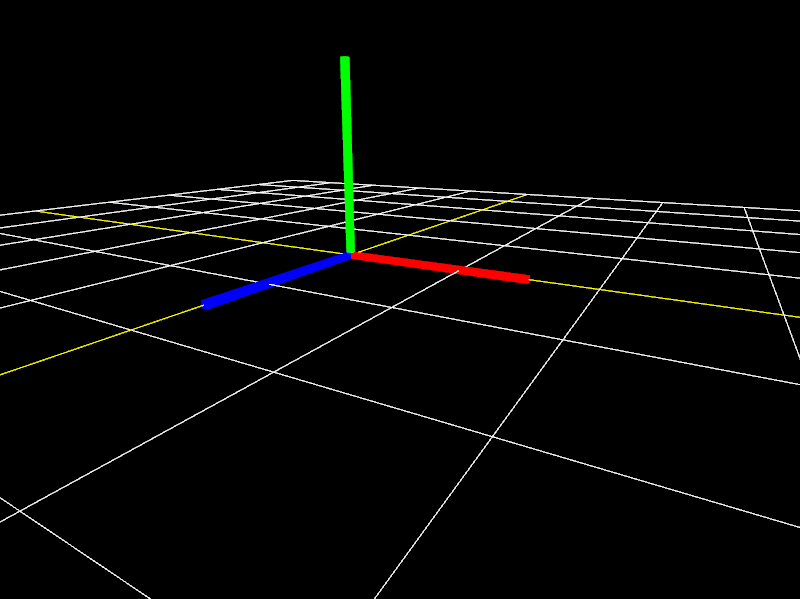
Confirm that you can see a white and yellow grid stretching out in front of the camera with red, green, and blue axes in the center.
If all goes well, the application should show the following scene:
Camera Rig
The final component is a special object called a rig that carries the camera as it moves in three dimensions.
In addition, the camera will be able to pan up and down without changing the direction of movement.
We can accomplish this by making a CameraRig class which extends the Group class and then adding a camera object to it as a child node.
Inputs related to movement will apply to the CameraRig object itself while inputs for panning the camera will apply as local transformations to the camera.
Keeping these as local transformations will make sure the camera always rotates with respect to its parent, the CameraRig.
![]() Try it!
Try it!
Inside the graphics/extras folder, create a new file called camera_rig.py.
Open camera_rig.py for editing and add the following lines of code:
# graphics/extras/camera_rig.py
from math import pi

from graphics.core.app import Input
from graphics.core.scene_graph import Group

class CameraRig(Group):
    """A camera that can look up and down while attached to a movable base"""
    # keyboard controls for movement
    KEY_MOVE_FORWARD = 'w'
    KEY_MOVE_BACKWARD = 's'
    KEY_MOVE_LEFT = 'a'
    KEY_MOVE_RIGHT = 'd'
    KEY_MOVE_UP = 'e'
    KEY_MOVE_DOWN = 'q'
    KEY_TURN_LEFT = 'j'
    KEY_TURN_RIGHT = 'l'

    def __init__(
            self,
            camera,
            inverted=True,
            units_per_second=1.5,
            degrees_per_second=60
    ):
        """
        Set the camera and motion configuration for this rig.
        Movement speed is defined by `units_per_second`.
        Rotation speed is defined by `degrees_per_second`.
        """
        super().__init__()

        # attach the camera as a child node of this group node
        self._camera = camera
        self.add(self._camera)

        self._move_speed = units_per_second
        self._rotate_speed = degrees_per_second

        # keyboard controls for looking
        if inverted:
            self.KEY_LOOK_UP = 'k'
            self.KEY_LOOK_DOWN = 'i'
        else:
            self.KEY_LOOK_UP = 'i'
            self.KEY_LOOK_DOWN = 'k'

    def update(self, input, delta_time):
        if not isinstance(input, Input):
            raise RuntimeError("Expected input to be of type Input.")

        # calculate distances for moving and rotating since the last frame
        move_amount = self._move_speed * delta_time
        rotate_amount = self._rotate_speed / 180 * pi * delta_time

        # move the rig body in all directions
        if input.is_key_pressed(self.KEY_MOVE_FORWARD):
            self.translate(0, 0, -move_amount)
        if input.is_key_pressed(self.KEY_MOVE_BACKWARD):
            self.translate(0, 0,  move_amount)
        if input.is_key_pressed(self.KEY_MOVE_LEFT):
            self.translate(-move_amount, 0, 0)
        if input.is_key_pressed(self.KEY_MOVE_RIGHT):
            self.translate( move_amount, 0, 0)
        if input.is_key_pressed(self.KEY_MOVE_UP):
            self.translate(0,  move_amount, 0)
        if input.is_key_pressed(self.KEY_MOVE_DOWN):
            self.translate(0, -move_amount, 0)

        # turn the rib body left and right
        if input.is_key_pressed(self.KEY_TURN_RIGHT):
            self.rotate_y(-rotate_amount)
        if input.is_key_pressed(self.KEY_TURN_LEFT):
            self.rotate_y( rotate_amount)

        # turn the camera to look up or down
        if input.is_key_pressed(self.KEY_LOOK_UP):
            self._camera.rotate_x( rotate_amount)
        if input.is_key_pressed(self.KEY_LOOK_DOWN):
            self._camera.rotate_x(-rotate_amount)
Make sure there are no errors and save the file.
The CameraRig class uses an instance of Input from core.app to handle keyboard inputs.
The WASD and QE keys control moving the rig while the JL keys will turn it left and right.
The IK keys then pan the camera up and down, depending on whether the inverted option is set or not.
Notice that the KEY_LOOK_UP and KEY_LOOK_DOWN inputs apply a rotation to self._camera while all the others apply to self, the rig itself.
Finally, let’s make our last test application to try out the camera rig.
Inside your main folder, create a copy of the file called test_9_2.py and change its name to test_9_3.py.
Open test_9_3.py for editing and add the following import statement to the list of import statements:
from graphics.extras.camera_rig import CameraRig
Scroll down to the startup method and delete the following lines of code:
        self.camera.position = (5, 2, 7)
        self.camera.rotate_y( pi/6)
        self.camera.rotate_x(-pi/10)
In place of the deleted code, add the following:
        self.rig = CameraRig(camera, inverted=False)
        self.rig.position = (5, 2, 7)
        scene.add(self.rig)
Scroll down to the update method and add the following code just before # render the scene:
        # handle inputs and animations
        self.rig.update(self.input, self.delta_time)
Save the file and run it with the command python test_9_3.py in the terminal.
Confirm that you can move the camera in all directions in addition to panning it up and down.
![]() Congratulations!
Congratulations! ![]()
You have now completed enough components to start creating some interesting 3D scenes.
What other components for programming interactive 3D apps can you think of?
In our final lesson, we will add several extensions of the Geometry class to our CG framework, such as polygons and cylinders, which are useful for modeling more complex objects.
Look forward to it!