3_Drawing Shapes
In this lesson, we add a class to our framework to simplify the use of vertex buffers and then use the class to draw shapes with multiple vertices and colors.
In our last app, we drew a single point with only a single vertex. But we need more than a single vertex to draw shapes. For example, triangles have 3 vertices, squares have 4 vertices, and hexagons have 6 vertices. As the number of shapes and their vertices grow, we need to make use of memory objects called vertex buffers to process the data collectively.
Using Vertex Buffers
Recall from test_2_2.py that the application stage of the graphics pipeline creates vertex buffer objects (VBOs) in memory, stores data in those buffers, and associates the data in those buffers with shader program variables. These associations are stored in a vertex array object (VAO) which we bind for use by the GPU. In our last test program, we had a single VAO but did not use any buffers with it. This time we will prepare an Attribute class which automatically binds vertex buffers, uploads data to them, and links them to shader variables so the shader can access the data. By encapsulating the management of vertex buffers in Attribute objects, it will become a lot easier to handle multiple vertices and draw complicated shapes.
Here is an outline of the class and the OpenGL functions it will use:
- First, we use
glGenBuffersto get a reference to an available buffer for the attribute. - Then we bind the buffer by passing its reference to
glBindBuffer. We also indicate that the the buffer is a vertex buffer by including theGL_ARRAY_BUFFERargument. - Next, we upload the attribute’s data to the buffer with
glBufferData. This function takes a binding target as a parameter, so passingGL_ARRAY_BUFFERwill tell it to use the currently bound vertex buffer. - Once the vertex buffer contains data and the GPU program is compiled, we can get a reference to the attribute’s variable in the GPU program and associate it with data. We do this with the
glGetAttribLocationfunction, giving it a reference to the program and the name of the variable. (The variable inside the vertex shader program specifies theinqualifier.) - Then we associate the variable to the bound buffer with
glVertexAttribPointer. This function needs the variable reference, the data type, and the number of components in the data. Basic data types likeintandfloathave just 1 component, but vectors will have 2, 3, or 4 components. - Finally, we enable using the association to read the data by calling the
glEnableVertexAttribArrayfunction and giving it the reference to the variable.
This all may sound complicated, but we only need to write code for it once the Attribute class. After that, we can easily gain all the benefits of this code by simply using instances of Attribute in our apps.
The Attribute Class
![]() Try it!
Try it!
In your core folder, create a new file called openGL.py.
Open openGL.py for editing and add the following code:
# graphics/core/openGL.py
import OpenGL.GL as GL
import numpy

class Attribute:
    """Manages a single attribute variable that uses data from a vertex buffer"""

    # maps data types to their associated vertex size and data type
    _ATTRIB_SIZE_TYPE = {
        "int": (1, GL.GL_INT),
        "float": (1, GL.GL_FLOAT),
        "vec2": (2, GL.GL_FLOAT),
        "vec3": (3, GL.GL_FLOAT),
        "vec4": (4, GL.GL_FLOAT),
    }

    def __init__(self, data_type, data):
        # data types are defined by the dict above
        if data_type not in self._ATTRIB_SIZE_TYPE.keys():
            raise ValueError(data_type, "Unsupported data type")

        self.data_type = data_type
        self.data = data

        # get a reference to a vertex buffer
        self.buffer_ref = GL.glGenBuffers(1)

        # send the data to the GPU buffer
        self.upload_data()
When we create a new vertex attribute, we give it data to store in a vertex buffer and specify the data type. The Attribute instance will get an available vertex buffer when it initializes and then immediately upload its data using the upload_data method which we will define below.
We also define a class variable called _ATTRIB_SIZE_TYPE to map data type parameters to their associated vertex size and component data types. The variable is a dictionary where each key is a valid parameter for self.data_type, and each value is a tuple containing the number of components and data type of each component in OpenGL. As a class variable, the dictionary is shared among all instances and we can use it both in the __init__ method and in the method we create later for associating variables with their data.
Add the upload_data method to the Attribute class.
    def upload_data(self):
        """Load data stored in this object into the associated buffer"""
        # convert data to numpy array of 32-bit floating point numbers
        data = numpy.array(self.data).astype(numpy.float32)

        # bind the buffer for use
        GL.glBindBuffer(GL.GL_ARRAY_BUFFER, self.buffer_ref)

        # store data in the currently bound buffer as a flat array
        GL.glBufferData(GL.GL_ARRAY_BUFFER, data.ravel(), GL.GL_STATIC_DRAW)
By putting this code in a separate upload_data method, we can easily update the data for the same attribute multiple times. This will be useful later when we create animations and interactive features. Before uploading the data, we need to make sure it is in the right format for GLSL: a one-dimensional array of 32-bit floating point numbers. The numpy library is very useful here with its implementation of arrays and ravel function which converts arrays to one dimension.
Next is another method for associating variables with their data, aptly named associate_variable. Once a variable association has been created, any changes to its data through the upload_data method will automatically be reflected at render time. This means we will only need to call associate_variable once for each attribute in an app, but the upload_data method will be called in every iteration of the application’s update loop.
After the upload_data method, add the associate_variable method below.
    def associate_variable(self, program_ref, variable_name, vao_ref=None):
        """
        Link the data in this object's buffer to a variable in a shader.
        The association will be stored in the given VAO reference if provided.
        Otherwise, the currently bound VAO will be used.
        """
        # get a reference for the program variable with the given name
        variable_ref = GL.glGetAttribLocation(program_ref, variable_name)

        # stop if the program does not use the variable
        if variable_ref == -1:
            print(f"No reference found for variable {variable_name}")
            return

        # bind the buffer for use just in case it hasn't been bound already
        GL.glBindBuffer(GL.GL_ARRAY_BUFFER, self.buffer_ref)

        # optionally bind a vertex array object if provided
        if vao_ref is not None:
            GL.glBindVertexArray(vao_ref)

        # get vertex parameters for this attribute's data type
        size, gl_type = self._ATTRIB_SIZE_TYPE[self.data_type]

        # associate buffer data with the found variable and store the
        # association in the currently bound VAO
        GL.glVertexAttribPointer(variable_ref, size, gl_type, False, 0, None)

        # enable use of buffer data for this variable during rendering
        GL.glEnableVertexAttribArray(variable_ref)
Before calling glVertexAttribPointer we need to bind both a vertex buffer object and a vertex array object. We bind the the vertex buffer with glBindBuffer using the stored VBO reference. As for the vertex array object, an app may bind a VAO itself, or it may provide a reference with the vao_ref parameter. In either case, binding both VBO and VAO is necessary for the current VAO to link data from the vertex buffer to the program variable. OpenGL manages the VAOs and associations once they are created, so we do not need to do anything more with the variable reference.
Hexagons, Triangles, and Squares
Now we are ready to draw shapes on the screen with multiple vertices and lines. By default, OpenGL draws lines only 1 pixel wide which can be hard to see on high resolution displays. On Windows, we can use a function called glLineWidth to set the thickness of the lines drawn by OpenGL in pixels. (We cannot use glLineWidth on MacOS because MacOS strictly enforces the core OpenGL profile, which only allows 1.0 as a valid parameter.)
A Single Buffer Test
Our first test application will use the Attribute class from above to draw lines between six points on the screen and create a hexagon. This time, the vertex shader program has a single variable position declared with the in qualifier so it will receive data from a vertex buffer. Instead of hardcoding the position data in the vertex buffer, we provide it through our own position_data variable and link that data with an instance of Attribute.
![]() Try it!
Try it!
Make a new file in your main working folder called test_3_1.py.
Open test_3_1.py and add the following test application source code.
# test_3_1.py
import OpenGL.GL as GL

from graphics.core.app import WindowApp
from graphics.core.openGLUtils import initialize_program
from graphics.core.openGL import Attribute

class Test_3_1(WindowApp):
    """Test the Attribute class by drawing lines between 6 vertices of a hexagon"""
    def startup(self):
        print("Starting up Test 3-1...")

        # the vertex shader position variable will get data from a buffer
        vs_code = """
        in vec3 position;
        void main() {
            gl_Position = vec4(position.x, position.y, position.z, 1.0);
        }
        """

        # th fragment shader will output fragColor to a buffer
        fs_code = """
        out vec4 fragColor;
        void main() {
            fragColor = vec4(1.0, 1.0, 0.0, 1.0);
        }
        """

        self.program_ref = initialize_program(vs_code, fs_code)

        # **WINDOWS ONLY** set a wider line width so it is easier to see
        GL.glLineWidth(4)

        # create and bind the vertex array object (VAO)
        vao_ref = GL.glGenVertexArrays(1)
        GL.glBindVertexArray(vao_ref)

        # initialize the hexagon vertices as attribute data
        position_data = (
            ( 0.8,  0.0, 0.0),
            ( 0.4,  0.6, 0.0),
            (-0.4,  0.6, 0.0),
            (-0.8,  0.0, 0.0),
            (-0.4, -0.6, 0.0),
            ( 0.4, -0.6, 0.0)
        )

        # set the number of vertices to be used in the draw function
        self.vertex_count = len(position_data)

        # create and link an attribute for the position variable
        position_attribute = Attribute("vec3", position_data)
        position_attribute.associate_variable(self.program_ref, "position")

    def update(self):
        GL.glUseProgram(self.program_ref)

        # use the line loop drawing mode to connect all the vertices
        GL.glDrawArrays(GL.GL_LINE_LOOP, 0, self.vertex_count)

# initialize and run this test
Test_3_1().run()
Run the application with the python test_3_1.py command in your terminal.
Confirm that a yellow hexagon outline appears on your screen.
Notice that we create an Attribute instance with our position_data variable and then link it to the vertex shader’s position variable with the associate_variable method.
This time, the glDrawArrays function uses the GL_LINE_LOOP mode to draw lines from one vertex to the next and then connect the last vertex to the first one. Here we use vertex_count from the startup method to tell it exactly how many vertices it should draw.
Now glDrawArrays can use a number of different OpenGL primitives to render the lines in different ways. In test_2_2.py, we used GL_POINTS to render a single point, but GL_LINES will draw a line between each pair of consecutive points, and GL_LINE_STRIP will connect each point to the next, stopping at the last point.
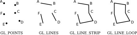
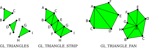
When we want to fill in the area between lines, we can use one of the triangle drawing modes. GL_TRIANGLES will fill in the area between every three points without any overlap. GL_TRIANGLE_STRIP will include the last two points of the previous triangle with the next point to create an adjacent triangle. Finally, GL_TRIANGLE_FAN connects every two points with the first point to create a fan-like array of adjacent triangles all sharing the same point.
It is also possible to combine draw modes with the same set of vertices by simply calling glDrawArrays multiple times. For example, if the update method has the next two lines of code, it will draw the lines first and then it will draw each point on top of the lines. (Although if you do this, the points will be difficult to see unless you increase the size of the points by calling glPointSize inside your startup method.)
        GL.glDrawArrays(GL_LINE_LOOP, 0, self.vertexCount)
        GL.glDrawArrays(GL_POINTS, 0, self.vertexCount)
A Multi-Buffer Test
In test_3_1.py we only used a single buffer with a single set of vertices for drawing a single shape. Drawing more than one shape will require more than one vertex buffer. The next test app demonstrates this by drawing a triangle and a square at the same time.
Even though the position data for the triangle and square will be stored in separate buffers, we will use the same vertex shader and fragment shader code to draw both shapes. We can do this because the rendering process for a triangle is essentially the same as the rendering process for a square. The only difference is the position data. In order to use the same shaders with the same position variable, we will make and store references to two different vertex arrays. Since VAOs store associations between buffers and variables, one VAO will associate the position variable to the triangle’s position data while the other VAO will associate position with the square’s position data. Then, in the update method, we use the stored VAO references to bind the associated VAO before calling glDrawArrays.
![]() Try it!
Try it!
In your main folder, create a new file called test_3_2.py.
Open test_3_2.py and add the following code.
# test_3_2.py
import OpenGL.GL as GL

from graphics.core.app import WindowApp
from graphics.core.openGLUtils import initialize_program
from graphics.core.openGL import Attribute

class Test_3_2(WindowApp):
    """Test multiple VAOs by rendering a square and a triangle together"""
    def startup(self):
        print("Starting up Test 3-2...")

        vs_code = """
        in vec3 position;
        void main() {
            gl_Position = vec4(position.x, position.y, position.z, 1.0);
        }
        """

        fs_code = """
        out vec4 fragColor;
        void main() {
            fragColor = vec4(1.0, 1.0, 0.0, 1.0);
        }
        """

        self.program_ref = initialize_program(vs_code, fs_code)

        # get a reference to a vertex array object for the triangle
        self.vao_triangle = GL.glGenVertexArrays(1)
        triangle_position_data = (
            (-0.5, 0.8, 0.0),
            (-0.2, 0.2, 0.0),
            (-0.8, 0.2, 0.0)
        )
        self.vertex_count_triangle = len(triangle_position_data)
        triangle_position = Attribute("vec3", triangle_position_data)
        triangle_position.associate_variable(
            self.program_ref, "position", self.vao_triangle
        )

        # get another reference to a vertex array object for the square
        self.vao_square = GL.glGenVertexArrays(1)
        square_position_data = (
            (0.8, 0.8, 0.0),
            (0.8, 0.2, 0.0),
            (0.2, 0.2, 0.0),
            (0.2, 0.8, 0.0)
        )
        self.vertex_count_square = len(square_position_data)
        square_position = Attribute("vec3", square_position_data)
        square_position.associate_variable(
            self.program_ref, "position", self.vao_square
        )

    def update(self):
        # the same shader program can render both shapes
        GL.glUseProgram(self.program_ref)

        # draw the triangle
        GL.glBindVertexArray(self.vao_triangle)
        GL.glDrawArrays(GL.GL_LINE_LOOP, 0, self.vertex_count_triangle)

        # draw the square
        GL.glBindVertexArray(self.vao_square)
        GL.glDrawArrays(GL.GL_LINE_LOOP, 0, self.vertex_count_square)

# initialize this test and run it
Test_3_2().run()
Run the application with the python test_3_2.py command in your terminal.
Confirm that a yellow triangle outline and a yellow square outline appear on your screen like in the screenshot below. (NOTE: On MacOS, the background may be red instead of black.)
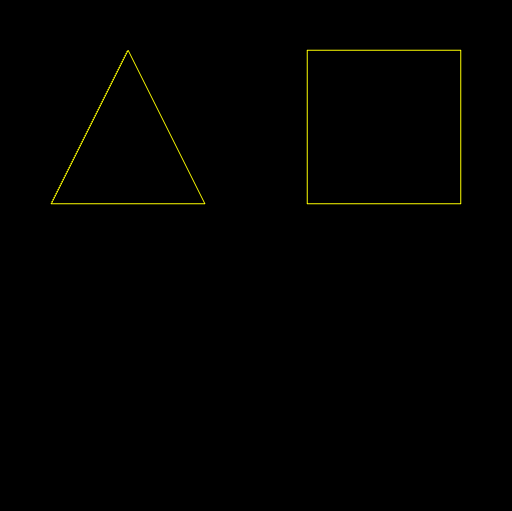
This time we specify which shape to draw by binding the respective VAO before drawing with glDrawArrays in the update method. In order to do this, we had to use different VAOs for the triangle and square when creating their position attributes inside our startup method. The associate_variable method allows us to pass the VAO reference to be bound rather than binding it ourselves in the startup method.
Passing Data Between Shaders
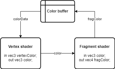
We can also use vertex buffers to hold color data in addition to position data. This requires a few extra steps since buffer data is first passed into the vertex shader, but color data is only used in the fragment shader. So we need to pass the color data from the vertex shader to the fragment shader.
Remember, in the OpenGL Shading Language (GLSL), variables have type qualifiers. In the vertex shader, in means the variable data comes from a vertex buffer and out means the data will go to the fragment shader. In the fragment shader, in means the data comes from the vertex shader and out means the data will be stored in another memory buffer.
In order to send color data from our application to be rendered by the fragment shader, we need to send it through a variable in the vertex shader. So the vertex shader will declare an in vertexColor variable and an out color variable. Then, the fragment shader must also declare an in variable with the exact same name and type as the out variable from the vertex shader.
Here is what our vertex shader will look like with the new variables:
# GLSL version 330
in vec3 position;
in vec3 vertexColor;
out vec3 color;
void main() {
    gl_Position = vec4(position.x, position.y, position.z, 1.0);
    color = vertexColor;
}
Note that the vertex shader does not change the color data in any way. It only assigns the values from the in variable to the out variable with color = vertexColor;.
Then, the fragment shader will look like this:
# GLSL version 330
in vec3 color;
out vec4 fragColor;
void main() {
    fragColor = vec4(color.r, color.g, color.b, 1.0);
}
The color data from the vertex shader is received with the in variable by the same name color.
(NOTE: The vertex shader uses [x, y, z] naming to access components while the fragment shader uses [r, g, b] naming. These are just conventions as they both access the components at indices [0, 1, 2] respectively.)
Now let’s create one more test app to demonstrate color data passing through attribute variables.
![]() Try it!
Try it!
In your main folder, create a new file called test_3_3.py.
Open test_3_3.py and add the following source code:
# test_3_3.py
import OpenGL.GL as GL

from graphics.core.app import WindowApp
from graphics.core.openGLUtils import initialize_program
from graphics.core.openGL import Attribute

class Test_3_3(WindowApp):
    """Test passing color data between shaders with a colorful hexagon"""
    def startup(self):
        print("Starting up Test 3-3...")

        vs_code = """
        in vec3 position;
        in vec3 vertexColor;
        out vec3 color;
        void main() {
            gl_Position = vec4(position.x, position.y, position.z, 1.0);
            color = vertexColor;
        }
        """

        fs_code = """
        in vec3 color;
        out vec4 fragColor;
        void main() {
            fragColor = vec4(color.r, color.g, color.b, 1.0);
        }
        """

        self.program_ref = initialize_program(vs_code, fs_code)

        # make points larger so they are easy to see
        GL.glPointSize(10)

        # create and bind a single VAO
        vao_ref = GL.glGenVertexArrays(1)
        GL.glBindVertexArray(vao_ref)

        # position data for each of the six points
        position_data = (
            ( 0.8,  0.0, 0.0),
            ( 0.4,  0.6, 0.0),
            (-0.4,  0.6, 0.0),
            (-0.8,  0.0, 0.0),
            (-0.4, -0.6, 0.0),
            ( 0.4, -0.6, 0.0)
        )
        position_attribute = Attribute("vec3", position_data)
        position_attribute.associate_variable(self.program_ref, "position")

        # color data for each of the six points
        color_data = (
            (0.5, 0.0, 0.0),
            (1.0, 0.5, 0.0),
            (1.0, 1.0, 0.0),
            (0.0, 1.0, 0.0),
            (0.0, 0.0, 1.0),
            (0.5, 0.0, 1.0)
        )
        color_attribute = Attribute("vec3", color_data)
        color_attribute.associate_variable(self.program_ref, "vertexColor")

        # both position and color VBOs have the same number of vertices
        self.vertex_count = len(position_data)

    def update(self):
        GL.glUseProgram(self.program_ref)
        GL.glDrawArrays(GL.GL_POINTS, 0, self.vertex_count)

# initialize and run this test
Test_3_3().run()
Run the application with the python test_3_3.py command in your terminal.
Confirm that you can see six different colored dots on your screen.
In test_3_2.py, we used two different vertex arrays to bind different buffers to the same program variable. This time we have two different program variables associated with two different buffers, so we can use a single VAO to store the associations.
Now what happens if we change the draw mode from GL_POINTS to something like GL_LINE_LOOP or GL_TRIANGLE_FAN? In that case, we can see OpenGL’s rasterization process in action as it interpolates the color values in between each vertex. Here, interpolation is a mathematical calculation of the RGB components for each pixel based on how far it is from the original vertices. It weighs the values of each vertex color value and combines them to get the final color values for each pixel.
For example, if a point $P$ is located three-quarters of the distance between a point with color $C_1=[1.0, 0.0, 0.0]$ (red) and a second point with color $C_2=[0.0, 0.0, 1.0]$ (blue), then its color $C_P$ would be one-quarter of $C_1$ and three-quarters of $C_2$. The result is a darker shade of blue:
\[\begin{aligned} C_P &=0.25 \cdot C_1+0.75 \cdot C_2 \\ &=0.25 \cdot [1.0, 0.0, 0.0] + 0.75 \cdot [0.0, 0.0, 1.0] \\ &=[0.25, 0.0, 0.0] + [0.0, 0.0, 0.75] \\ &=[0.25, 0.0, 0.75] \end{aligned}\]The result of filling a shape with triangle draw modes will interpolate the colors between vertices, effectively creating a gradient effect. Now if we want all the points and the shape to be filled with the same color, we just need to change all the vertices of our color_data variable to be the same value.
Next time, we will create a new class that we can use to easily create solid color shapes. The same class will also allow us to create animations and interactivity easily as well. Look forward to it!